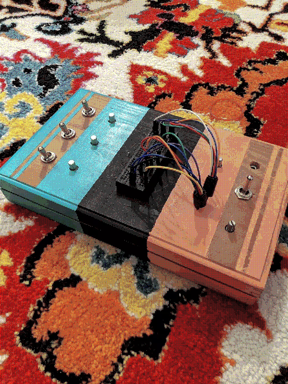
sanfreo euroling
the sanfreo euroling is a  diy-synthesizer. i made it as part of a
dogbotic course. it features:
- a square oscillator
- an internal clock
- three low frequency oscillators (LFOs)
- a binary divider for creating octaves
- a multiplexer for creating rhythms
- “chaos modes”
- external clock sync
- an exposed mini patchbay
overview
The layout is exposed into three components
- the sonic engine: the oscillator and binary divider that creates octaves for sound
- timing engine: the external clock, the internal clock, and three LFOs for sequencing
- the interface: he the exposed breadboard for creating sequences and rhythms
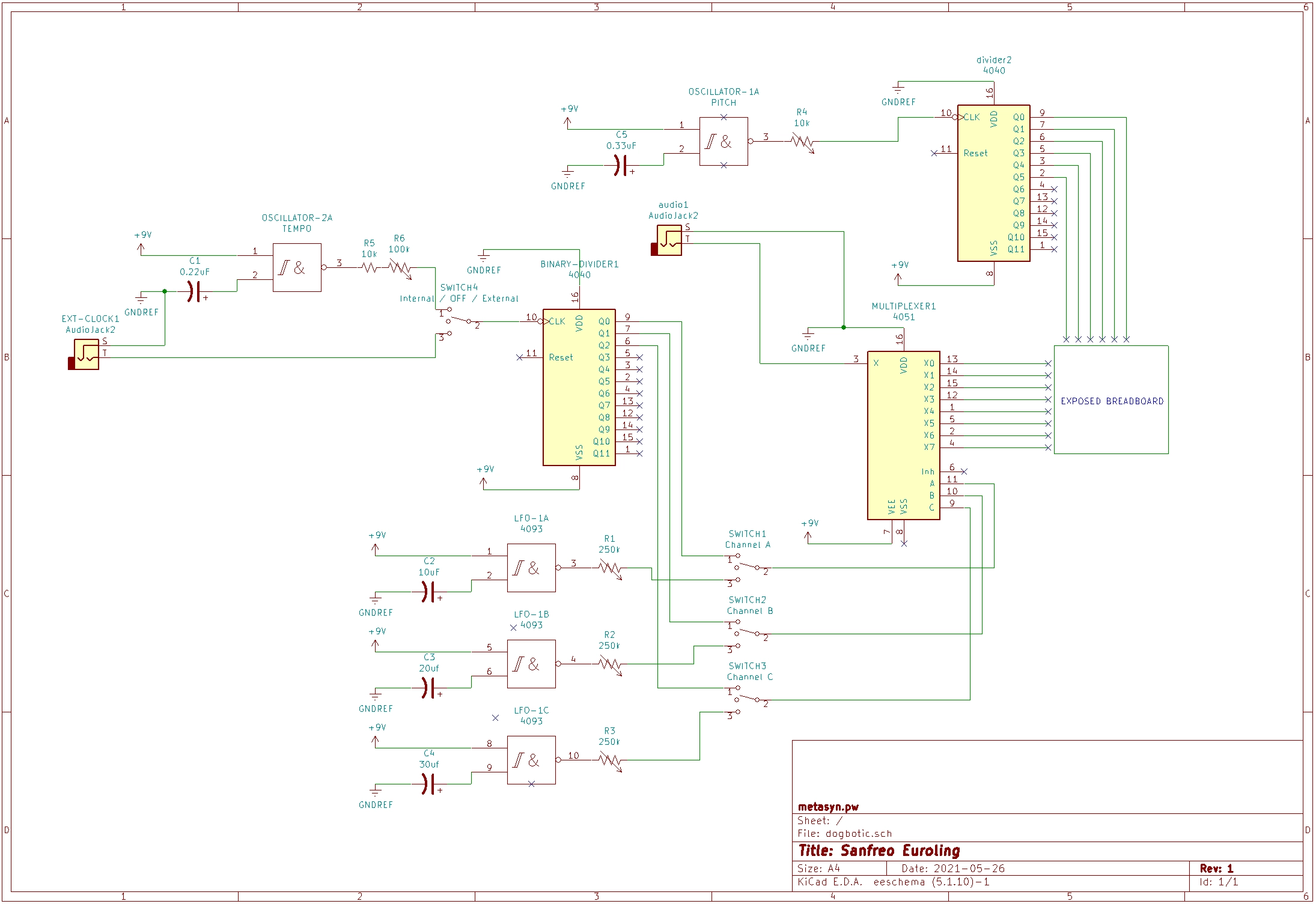
In the schematic below:
- the sonic engine can be seen toward the top and top right.
- the timing engine can be seen on the left and bottom left
- the interface can be seen in the middle and right where the two meet
sonic engine
the sonic engine part of this synthesizer is an incredibly simple square wave generator. it utilizes only three components:
- a NAND gate
- a capacitor (0.33uf or so)
- a potentiometer
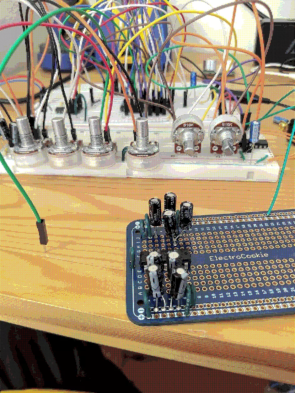
the potentiometer functions as a way of changing the pitch as well. I originally wanted to add an active low pass filter but instead decided to embrace the intense, unfiltered sound created by this circuit.
this oscillator then feeds into a binary divider. it divides the signal by 2, 4, 8, 16, 32, and 64, each into their own signal. this creates a variety of octaves for us to work with, instead of a single pitch. so, the sonic engine gives us 6 outputs to work with.
timing engine
the timing engine has one of two inputs:
- an oscillator (just like the sonic engine, but with a larger capacitor to slow down the rate)
- an external clock (fed via a 1/8” or 3.5mm jack)
these two inputs are selected via a switch. from there, this timing is fed into a binary divider which divides the clock by 2, 4, and 8 respectively so, from this, we end up with three different clocks. these, when treated as digital signals (that is, binary in this case), can be used to specify a number between 0 and 7 (or 8 steps total). for example, here is our clock value, and our divisions:
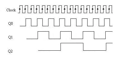
(image from here)
if we take the first division as our first binary digit, the second as our second, and the third our third, we end up with a 3 bit value that can expectedly represent one of 8 total states. check out this page if you need a refresher on binary counting. these binary signals we have are fed into three switches.
the other half of these switches are given the signals from three separate LFOs. each LFO has its own potentiometer to change the rate that it is oscillating at (just like the pitch for our earlier oscillator).
the three switches then feed into the multiplexers pins that control which “step” our sonic engine is triggering next. each LFO can be turned on individually, allowing you to control one “bit” of information that is determining the step position with a new signal. this allows for you to add some more interesting rhythms that are not simple divisions of the input clock, and can be used to create more generative and random sounding sequences. the multiplexer then takes these three inputs and produces 8 output signals.
interface
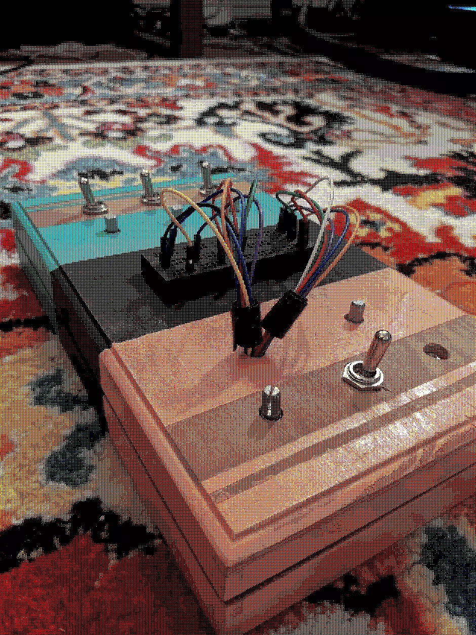
from the sonic engine, we have 6 outputs (the 6 different octaves of the original oscillator). from the timing engine, we have 8 steps that will be triggered every so often. when they are triggered, they will let their current out through the multiplexers common output into our audio output. the 6 pitches and 8 steps are each assigned to their own cord which comes out of the top of the synthesizer. there are 6 columns of vertically connected breadboard strips. by patching different combinations of the cables, you can create different sequences and rhythm.
lastly, the audio out is a 1/4” (7mm) jack, and the whole thing is powered by a 9V battery.
schematic
the schematic is missing one voltage divider with a potentiometer on the audio out. this is used to decrease the volume, because before the audio signal was way too high / loud /hot.
enclosure
i purchased an old wooden box at salvation army for $2 USD. i drilled holes in it, then painted it.
chaos modes
each switch was meant to have an OFF position when set to the middle setting. however, something about this circuit causes a lot of noise to end up being picked up. i have yet to identify how / where its triggering. however, if you leave the LFOs on chaos mode and set the main clock input to be on chaos mode, you get a lot of unexplainable, unexpected behavior. chaos!
naming
The “codename” system of naming modules and synthesizers was pervasive for a long while during the 20th centuyy, but as when there is any pervasive system, there is also an equally perverse reaction to it. Using words to name synthesizers, as a reaction to the abstract codename, led to some quite “gonzo” names, as well as serious and profound re-contextualization of the role of the synthesizer. By naming they create a space around the new word, with specific nodes of meaning that would be implied to the reader of science fiction, but also real electronic interpolations between these nodes; a web of meaning modulations is created around the name.
— Peter Blasser, STORES AT THE MALL
i think one of the interesting things about this synthesizer is the way you can mess with the rhythm with the three LFOs. otherwise, i think the interface reminds me of a eurorack synthesizer. i also love the english suffix -ling, as in duckling, cutling. and so:
-
san = three
-
fre = frequency
-
o = oscillators
-
euro- (as in eurorack)
-
-ling (as in the diminutive)
learnings
- triple check before soldering an IC to a board
- quadruple check before desoldering anything - sometimes its easier to simply cut a wire somewhere…
- go slow on your case / enclosure. way harder to replace than a resistor or random component!
todo / in progress
- add latch to ensure the case doesn’t accidentally open
- add rubber feet to the bottom
referenced by:  diy-synthesizer


 learn-orca
 learn-uxn
